Dialup Adventures Part 1
Why run dialup in $CURRENT_YEAR?
Though we often forget it, dialup is what so many of us in the computer industry began with. The circumstances of transmitting digital data over a network designed to transmit only voice was enough of an accomplishment, but most have no grasp of exactly how impressive it is to hit 56k over those same lines. The dialup tone we all know and love reveals some of this complexity - ranging, filtering, training, etc.
The limitations of this approach, numerous as they are, provided a fixed set of parameters to network protocol design. There’s nostalgia to be noted here, and I think most of us can admit we have rose-colored glasses about that time. Regardless, I sought to understand first-hand how exactly “digital dialup” works, and purchased some gear to make it happen.
Equipment
Access Server / Modem Bank - Cisco AS5300
First, we’ll need a modem bank, a device to accept the incoming calls and speak dialup protocols over them. Many years ago I worked at an organization which ran a small-scale dialup ISP for their customers; we used a Portmaster 3 device and it seemed to serve us well. Around the time I was looking to purchase one however, there were none on the market which had the right combination of features, price, and shipping cost.
What was available was a Cisco AS5300 for $50, fully kitted out and in good working order. The unit came equipped with 108 internal MICA modems, 4x T1 ports, and a pair of ethernet ports at 100Mbps and 10Mbps respectively. This is obviously way more than I’d need just to play around, but it was cheap and fit the bill. I placed the order, paid just about as much in shipping to get it here as I paid for the appliance, and waited.
ISDN PRI breakout - Adtran Total Access 900e Series

Due to the way 56k connection speed standards (V.90, V.92, X2, K56Flex) require a complex Pulse Code Modulation (PCM), an analog-to-digital conversion anywhere along the phone line would cause problems. That means access servers intended for this speed are meant to connect to the telephone network with digital connections rather than a standard analog FXO phone line port. Optimally, these are provided via ISDN PRIs carried over T1s/E1s, each holding 23 simultaneous calls over B-channels, plus a D-channel for signalling. (There’s a discussion to be had here about DMI, RBS, and other such systems reducing the potential top-end bandwidth but that’s for another time). These trunked connections are great for use at a “real” dialup ISP, not so great for setting up at home. I’d need a device to break out the ISDN PRI into analog phone lines.
As I was browsing a local electronics recycler, I happened across a pair of Adtran Total Access 900e series devices that had been recently removed from a VoIP install. These are fairly flexible devices, and I’ve generally seen them used to translate between a PRI phone trunk and a SIP trunk, either because the carrier offers a PDH / TDM setup and the user wants a SIP trunk to a modern PBX, or connecting a TDM-capable PBX to a less-expensive “over the top” SIP offering.
These devices also carry a handful of FXS ports, intended for direct connection to an analog phone line device. These provide the standard “phone service” one would expect to get on a local loop - dialtone, DTMF digit interpretation, ring voltage, etc. This device will then allow an analog FXS port to dial across to the Cisco, which is fully digitally connected using the ISDN PRI to the Adtran. This ought to be digital enough to support the proper carriage of PCM, and ergo 56k.
Client modems - Thinkpad Internal

The easiest accessible modem I had lying around lived built-in to an old, trusty Lenovo T61 with a Core 2 Duo. It happened to be running Windows XP from previous adventures configuring a Toshiba Strata CTX100 PBX. I also snagged a pair of USRobotics Megahertz 56k PC Card modems from the local electronics recycler just for some variety, and installed those into the same laptop, though Windows XP refused to use them. Dialing them manually from Linux resulted in connection speeds slower than the Lenovo’s internal modem, so YMMV.
Setup
Analog lines
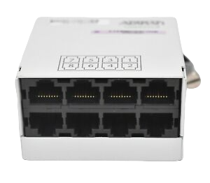
First, we’ll start with the simple stuff: getting the FXS ports set up on the Adtran. I used a T1 breakout for this, which is not at all for this use case, but some careful use of a multimeter and referencing T1 pinouts online allowed me to make a cable that converted each port on this breakout into 2x analog phone lines.
Configuration was straightforward enough - after clearing the config on the device, it’s pretty much two lines of config to turn up an FXS port connected to internal extension 200:
interface fxs 0/1
  no shutdown
voice user 200
  connect fxs 0/1
Connecting a phone to the port, I hear dialtone, nice! Let’s turn up another one:
interface fxs 0/2
  no shutdown
voice user 201
  connect fxs 0/2
Dialing between them gives me a functional basic phone call. Great! Let’s get the ISDN PRI up next.
T1 base layer
T1s are a flexible base layer for a few protocols / practices which can be laid overtop. One can use a T1 for data, phone calls, both at the same time, and more. A number of different practices exist for how to arrange these, such as timing, framing, line coding, call signalling, etc.
While there are a number of ways to set up a T1 for phone calls, the most important part is that we’ll need to match the configuration between the Cisco and the Adtran. There are a few parameters that we’ll need to line up:
- Timing: one device must lead the other in a clock reference. We’ll set one to have clock source internal, and the other to follow the line clock. In a “real network” the clock generally comes from the service provider downwards.
- Framing: both devices must match in the framing of the T1. I’ll use ESF (Extended Superframe) rather than SF for its CRC data integrity capability and the ability to avoid Robbed-Bit Signalling, which would reduce our line capacity.
- Line code: both devices must match how bits are put onto the wire. Our options are AMI (Alternate-mark inversion) and B8ZS (Binary Eight Zeros Substitution). Given my trunk will be 99% empty, using B8ZS which provides better clock recovery seems pertinent.
- Timeslots: TDM interfaces like a T1 can be split by their timeslots, so that some can be used for voice and others can be used for data, etc. In this case, we’ll be using all timeslots for voice.
So to summarize, our T1 is configured as Adtran leading the clock signal, Extended Superframe, B8ZS line coding, all timeslots. Adtran and Cisco differ in the hierarchy of their configuration; for example, Adtran’s timing-source is set globally and references an interface while the Cisco sets a “I’m timing primary” flag at the interface level. These two statements mean the same thing, they’re just said differently.
# Adtran

timing-source internal
interface t1 0/3
  # Create a device-global group of all timeslots on this T1, called tdm-group 1.
  tdm-group 1 timeslots 1-24 speed 64
  framing esf
  coding b8zs
  no shutdown
# Cisco

controller T1 0
 framing esf
 linecode b8zs
 # Use this controller as the device-global primary timing reference
 clock source line primary

 pri-group timeslots 1-24
T1 call signalling
To then utilize our T1’s base layer, we need to configure how the two devices will pass call setup and teardown information, dialed numbers, and other control information between them.
- Signalling: both devices must match how calls are setup and torn down, dialed numbers are signalled, etc. We’ll use ISDN for its ability to give us the full 64kbps channel.
- ISDN switch type: Different versions / countries used slightly different ISDN dialects. We’ll choose 4ess as it’s a commonly supported version for US equipment.
- ISDN Role: one device is the “network”, the other is the “user”. The Cisco is only capable of being a “user”, so we’re fixed in our decision here.
# Adtran

interface pri 1
  isdn switch-type 4ess
  # Associate the physical interface & group of timeslots
  connect t1 0/3 tdm-group 1
  # This device is the provider-side
  role network b-channel-restarts disable
  no shutdown
# Group up PRIs collectively
isdn-group 1
 connect pri 1
# Cisco

isdn switch-type primary-4ess
# Controller T1 0's channels are available as Serial0:X since we used the pri-group statement above, :23 references the "D" channel, the ISDN control channel
interface Serial0:23
 no ip address
 # Incoming calls are destined for modems
 isdn incoming-voice modem
 # Send incoming calls to the Async-Group 1 for the modem to handle (we'll configure in a bit)
 dialer-group 1
 isdn switch-type primary-4ess
Call routing
On the Adtran only this time - we need to tell it that a voice “trunk” exists, and that dialed numbers can be found on the other side
# Adtran

# A custom dial-plan so that it stops waiting for digits after we've typed 3, beginning with a 1
voice dial-plan 1 user1 1XX
voice trunk T01 type isdn
  # Select the T1's channels from the top down
  resource-selection circular descending
  # Connect the isdn-group 1 we created earlier
  connect isdn-group 1
  # Start sending audio through before the answer occurs
  early-cut-through
  # Autodetect modems and disable echo, etc
  modem-passthrough
  # Manual disabling of voice-oriented features
  no nls
  no echo-cancellation
  # Keep our packets short and don't delay them more than we have to
  rtp frame-packetization 10
  rtp delay-mode fixed
  rtp packet-delay nominal 10
  rtp packet-delay maximum 40
# Trunks are grouped for routing in Adtran's config, but we only have the one
voice grouped-trunk ISDN
  trunk T01
  # Internally, any calls destined for 1XX go to this trunk
  accept 1XX cost 0
Serial / PPP
We’re almost there! With our modems live and listening on the phone lines, let’s connect them to the internet
# Cisco

# Allow for classless inter-domain routing, moving our subnetting rules past 1996.
ip classless
# Create an IP address pool for IPs to hand to our clients
ip local pool dialin_pool 100.64.0.2 100.64.0.254
# Assign the first IP in this block for ourselves on a virtual interface
interface Loopback0
 ip address 100.64.0.1 255.255.255.0
# Create a route out of the Cisco onto the local network
interface FastEthernet0
 ip address 192.168.1.2 255.255.255.0
 duplex auto
 speed auto
!
# From the local network out to the internet
ip route 0.0.0.0 0.0.0.0 192.168.1.1
# Set up all modem serial lines as modems, allow users to automatically start PPP
line 1 108
 modem InOut
 autoselect ppp
# When calls come in, assign these PPP/IP settings
interface Group-Async1
 # Borrow the loopback's IP
 ip unnumbered Loopback0
 encapsulation ppp
 async mode interactive
 # Use our dialin_pool to assign IPs to our users
 peer default ip address pool dialin_pool
 # Allow for compression over PPP via MPPC, Microsoft's compression protocol
 compress mppc
 # Allow for users to use CHAP or PAP when they call in
 ppp authentication chap pap callin
 # Set users' DNS to 8.8.8.8
 ppp ipcp dns 8.8.8.8
 # These rules apply to serial lines 1 to 108 (our modems)
 group-range 1 108
Creating users
We’ll keep it simple since this is a small-scale test setup - in the real world, you’d authenticate users via RADIUS or TACACS+ to a remote server, likely from your fleet of dialin servers. Today, we’ll use our local authentication database.
# Use the new AAA model
aaa new-model
# Create user CISCO with the password CISCO - we'll use this to log into our dialup
username CISCO password CISCO
Testing
We’re ready for a test! Start simple: use a phone and dial 111 (or any other 3 digit number starting with 1). You should be dialed into a modem and hear its sweet screeching tones. If not, you’ll need to enable some debugging on the Adtran and Cisco and figure out where your call isn’t making it through.
Connect!
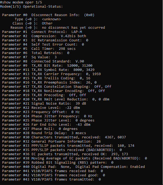
Set up a client modem on an FXS port on the Adtran. When ready, you’ll dial 111 (or any other 3 digit number starting with 1), and the username and password will be CISCO in all caps. With any luck, you should be able to successfully dial! This configuration has successfully achieved just shy of the maximum possible V.90 rate (53333kbps) in my testing, which means it’s far better than 99% of people ever saw in production.
What now?
I’d like to hit 53333 down, and maybe get V.92 running. Once that’s up, I’ll try getting multilink up and running - that is, bonding multiple dialup modems & phone lines for increased speed - an expensive luxury when dialup was prevalent.
There are a few other projects I can take on with this. One is to get my Sega Dreamcast linked up at proper 56k. While games will work fine at V.34 rates, going almost twice as fast is fun for using web browsers and the like. I also have a Apple Powerbook 140 with a 30-year old HDD that needs some love, but it’d be fun to connect to modern systems with its 2400 baud internal modem.
The other thing I’ve always wanted to test: running 56k dialup over a SIP connection. Many people have said it’s impossible, you’d be lucky if it trains up at 14.4k, there’s no way that V.90 would pass through even a μ-law encoder, etc. Despite all that, I’ve never seen someone “put their money where their mouth is” and try it.
Turns out, they’re wrong, but that’s a story for part 2.